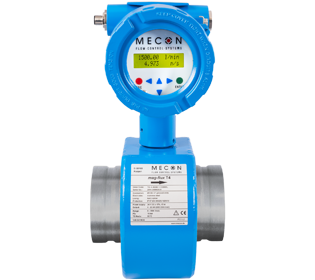
Mag-Flux ® T4
Magnetic Inductive Flow Meter Specifically for Use in Stationary Fire Safety Applications – Sprinkler Systems
With the Mag – Flux® T4 , CMC Fire Solutions features advanced flow meter sprinkler systems consistently and presents a solution with a fast 16-bit microcontroller and 4-20 mA electrical output. As a result, the Mag – Flux® T4 is easy to integrate into existing remote monitoring systems, and measurements can be evaluated in a control center.
For installation, the device offers an impressive range of connection options, e.g. flange, threaded or grooved connections. In fact, Mag – Flux® T4 is the only product with a VdS approved grooved connection. The measurement accuracy is always ± 0.5%.
Special features:
- Fully welded steel accessory.
- Fast signal processing with a 16-bit microcontroller.
- Fixed measuring ranges.
- Compact or separate design.
- Easy installation thanks to the coupling connection.
- Short input and output selections.
- Simple electrical connection through M12 connector.
- 4-20 mA output.
- Short delivery times.
Fluid condition:
| Medium, state of aggregation | Water, liquid |
| Minimal conductivity | > 20 µS/cm |
| Design / material Execution | Fully welded steel valve |
| Flow limits | 0.1 – 10 m/s |
| Sensor materials Measuring tube Coil Gap Coating measuring tube Electrode material |
Stainless steel Steel Hard rubber, PTFE Stainless steel / Hastelloy |
| Corrosion protection class | C2 (slightly polluted atmosphere, dry climate) |
M1 transducer
| Housing material | Die-cast aluminum housing |
| Electrical data Auxiliary power Power input |
230 VAC. – 15% / + 10%, 50/60 Hz 115 VAC. – 15% / + 10%, 50/60 Hz 24 V DC; ± 15% 10 W |
| Analog output | Active 4-20 mA current output |
| Influence of ambient temperature. | ± 0.1% por 10 K |
| Load | Standard: ≤ 600 0hm |
| Dipping | 3 s |
| Infiltration suppression | 0.1 m/s |
| Monitor Line 1 Line 2 |
Flow in l / min. or USGPM Flow velocity in m / s or ft / s |
| Room temperature | – 1 ºC to + 50 ºC, below 0 ºC, the readability of the LCD screen is limited |
Technical data
Reference conditions
| Fluid temperature | + 10 ºC a + 30 ºC |
| Room temperature | + 20 ºC a + 30 ºC |
| Heating time | 30 min. |
| Straight tube lengths | Inlet section 5 x DN Outlet section 2 x DN Well centered Properly grounded |
Flow Sensor / Transducer
| Measuring principle | Synchronized field DC |
| Entry Connection process / Nominal diameter | Thread connection G½ ”- G2” Coupling connection 50/2 «- 300/12» Float connection EN 1092-1 DN 15 – DN 300 |
| Measurement process Measurement error Repeatability | ± 0.5% of the measured value from 1 m / s to 10 m / s ± 0.4% of the measured value + 1 mm / s from 1 m / s ± 0.15% of the measured value from 0.5 m / s to 10 m / s |
| Mounting position Inlet section Outlet section |
5 x D 2 x D |
| Fluid temperature | + 4 ºC a + 50 ªC |
| Room temperature | + 1 ºC a + 50 ªC |
| Pressure limit | Threaded connection: max 16 bar Coupling connection: max 16 bar PN 16 flange connection: max 16 bar DN 65 – DN 300 PN 25 flange connection: 25 bar maximum DN 200 – DN 300 PN 40 flange connection: 25 bar maximum DN 15 – DN 150 |
| Protection type | IP 67 |


